
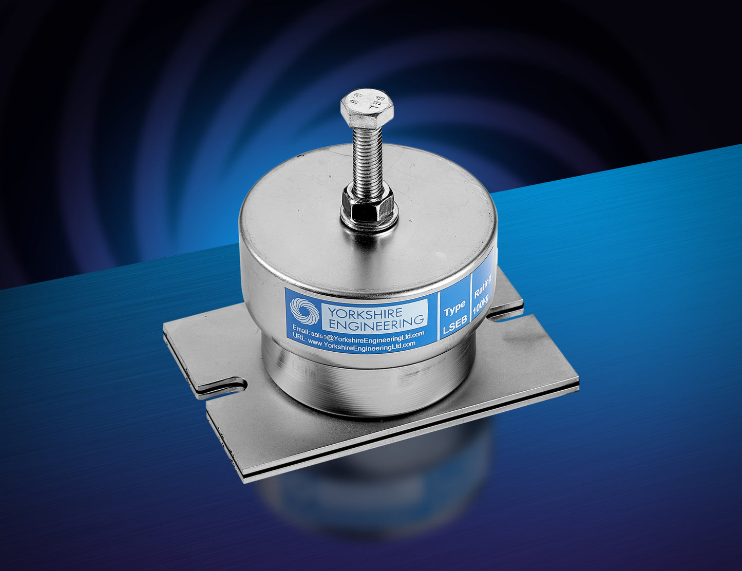
TYPE LSE-B
TYPE LSE-B
- Load range between 75-600 kg
- Incorporates nest of springs at higher loads
- Stiffer structure, used in locations where high damping is required.
- Maximum deflection of 25mm
- Low Profile
- Enclosed between housing to provide protection against debris


Couldn't load pickup availability
PRODUCT DESIGN FEATURES
The design gives them corrosion resistant properties enabling these AV mounts to provide long maintenance free service with a wide range of environmental conditions.
HOUSING:
The housing is based on two pressed steel cups and a foot plate. The housing is available in zinc coated mild steel and stainless steel options.
ENGINEERED SPRINGS:
The springs are individually load rated. They are supplied as multiple spring combinations to meet a wide variety of load requirements. This enables the AV mounts to optimally match the load distribution.
BASE PLATE AND NEOPRENE:
ANTI-SKID PAD:
The baseplate has a neoprene pad on the underside. This improves the clamping to typical surfaces, helping to maintain stability. This ensure that the AV mount has a secure base.
SNUBBER RING:
In an ideal world the AV mounts will never become unloaded or see side loads. The snubber ring prevents metal to metal contact when there is non-ideal installation, significant force excursions or seismic events. Compressing the snubber affects the AV mount behaviour so should not be permanent – for example over-compression of the springs using the levelling screw.
BUILT IN LEVELLING SCREW:
The levelling screw is used to ensure that the machine is level and can be used to accommodate for limited height adjustment. If significant height adjustment is required then shims or packers should be used at the bottom or top of the AV Mount.

TECHNICAL information TYPE LSE-B
AV-MOUNT Selection criteria:
Selection Procedure:
Anti-Vibration (AV) Mount Selection Criteria : Selection of correct mount for rotating equipment.
• Calculate the static point load at each proposed mount location.
• Select a mount with a rated load rating greater than the calculated point load.
• Use “Percentage Load vs AV Mount Deflection” graph to calculate static deflection (mm) or estimate the deflection (mm) using the “Mount Rating/Deflection” table.
• Knowing the proposed deflection (mm) read off the graph showing “% Isolation Efficiency Contours” to calculate the expected isolation that the AV Mount will give at equipment running speed.
NOTE : In general, an isolation efficiency greater that 90% is desirable.
Example:-
A fan weighing 376kg is to be supported on Qty 4 off AV mounts. The load will be equally distributed.
Machine (fan) running speed 1500 rpm.
Load per mount = 94kg (376/4)
Selecting an LSE-B 150 mount (150Kg rating), the load is 63%.
Deflection of AV mount at 60% is approx. 16mm.
The % Isolation Efficiency Contours show that isolation = 97.5% :
RECOMMENDED

Alternatively, If an LSE-B 500 is proposed,
Load = 19% with expected deflection of 4mm.
% Isolation ~90% :
NOT RECOMMENDED
For more complex loads, Yorkshire Engineering Ltd has in-house software available to provide optimum solutions

Installation Instructions

Depending on the application, the AV mounts need to be selected within the correct weight range.
The AV mounts are to be placed on a level surface with the levelling screw, nut and washer removed. Each mount is to be placed in their desired locations before loading them.

Align the holes of the anchor positions of the machine with the threaded holes of the AV mounts, so that they are concentric to each other for the best possible isolation location.
Depending on the distribution of load being applied, the AV mounts may not deflect evenly. This is can be accounted for by adjusting the AV mounts.
With the locknut wound close to the screw head insert it into the threaded hole.

When the screw is inserted, the outer cup rises allowing the equipment to be levelled.
Mounts with highest static deflections must be adjusted first.
When equipment is level, tighten the lock nut.

To prevent the equipment moving on the floor/support, each mount must be secured into place, by bolting through the slotted base plate.
